The latest from KODE
Your resource to everything you need to know about smart building operating systems
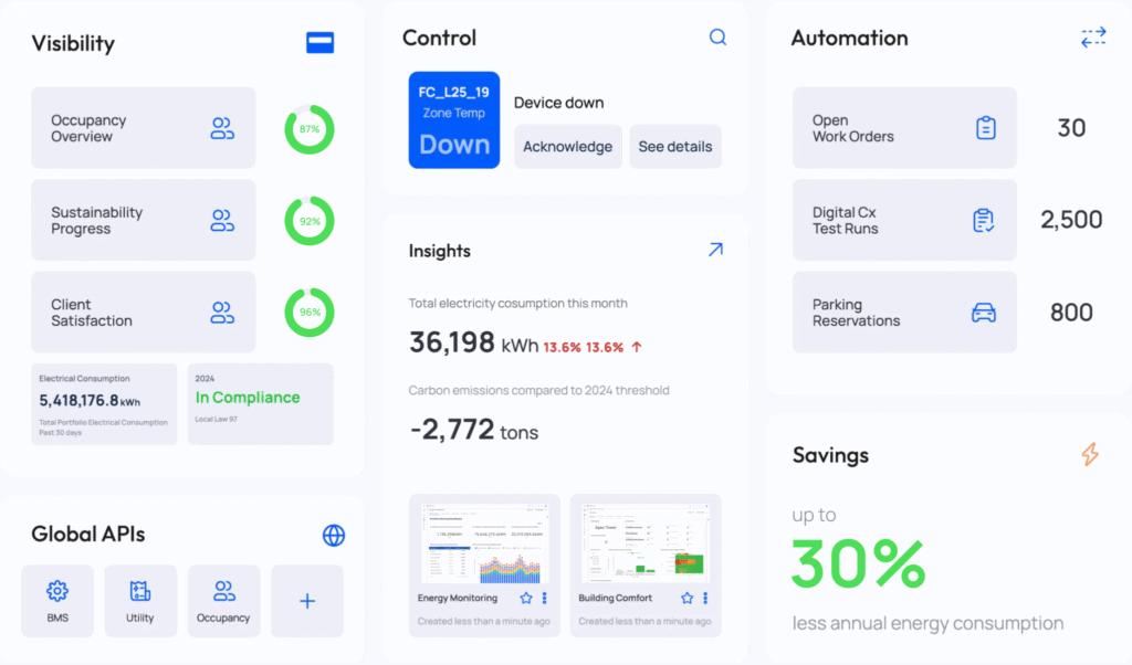
ResourcesThe KODE Mobile App puts the power of building management in your hands. Access real-time insights, control critical systems, and stay connected to your portfolio—all from a user-friendly app designed for on-the-go efficiency.
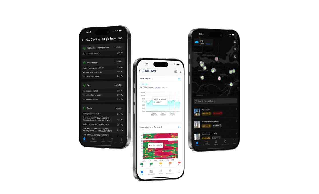
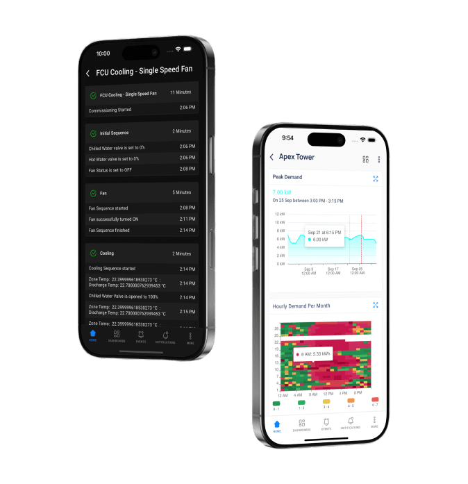
Stay in control of your building systems, including HVAC, lighting, and more, from anywhere using your smartphone.
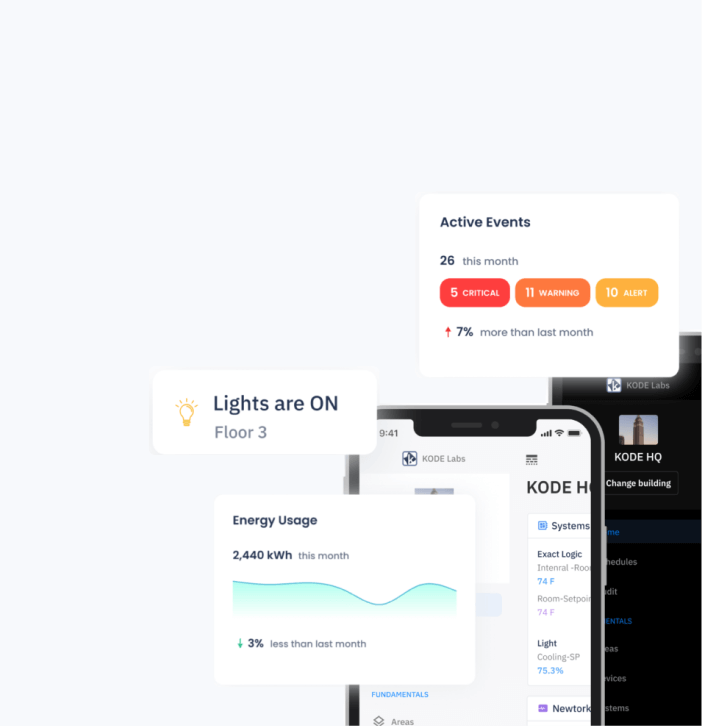
Gain complete visibility into the performance of all integrated building systems and IoT devices with powerful visualization tools.

Detect and resolve system issues in real time with actionable alerts, all accessible from your smartphone to keep systems running smoothly.

Verify system functionality and compliance with a digital commissioning tool you can use anytime, anywhere, on your mobile device.
Enjoy the full functionality of KODE OS in the palm of your hand, ensuring seamless operation, immediate response, and ultimate convenience for on-the-go building management.


KODE OS itself is quite complex, connecting every base building system, IoT and third-party app, to not only visualize everything in one screen but actually optimize building operations altogether.
Building operators can see their systems performance in real time, schedule tests to run automatically, and view performance reports at their convenience.
The 2.5D View in KLayout is a powerful visualization tool that extrudes 2D layout layers into a 3D-like perspective. It is primarily used to inspect material stacks and vertical layer relationships, which can be difficult to visualize in a standard flat view. Core Requirements & Setup
OpenGL Support: The 2.5D view is only available if your KLayout version was compiled with OpenGL support.
2.5D Scripting: To use the tool, you must create a script that defines how the layers are stacked and extruded. These scripts use a variant of the DRC (Design Rule Check) language.
Performance: The practical performance limit is currently around 100,000 polygons. How to Use the 2.5D View
Create a New Script: Go to Tools > 2.5d View > New 2.5d Script. This opens a new script template in the macro editor.
Define Extrusions: Use specific DRC functions to build your stack: z(layer, [options]): Extrudes a specific layer.
zz([options]) block : Groups multiple z statements to create complex 3D material geometries.
Run the View: Click the Run button in the macro editor or select your script from the Tools > 2.5d View menu.
Sync with Layout: The 2.5D window displays the section currently visible in your main layout view. If you close the window, you can reopen it via Tools > 2.5d View > Open Window. Navigation & Controls
Rotation: Drag with the right mouse button to change the viewing angle (azimuth and elevation).
Movement: Drag with the middle mouse button to pan the view or use the arrow keys.
Zooming: Use the mouse wheel to move the camera forward/backward, or Ctrl + Mouse Wheel to magnify the layout.
Exaggerate Height: Use the Z-axis zoom slider (on the right) to exaggerate height variations, which is helpful if the real height profile is too flat to see clearly. Visual Customization
Colors & Visibility: The 2.5D view inherits colors directly from your active KLayout Layer Properties. If you hide a layer or change its fill color in the main window, the 2.5D view updates accordingly. klayout 25d view
Net Tracing: While primarily for geometry, it is possible to export a specific net (e.g., from the Net Tracer) to visualize its path through different vertical layers. Colors in the 2.5d View - KLayout Layout Viewer And Editor
allows you to visualize a 2D layout in 3D by extruding layers vertically based on a script
. This is particularly useful for verifying material stacks, such as MEMS devices or CMOS metal layers. 1. Prerequisites OpenGL Support
: KLayout must be compiled with OpenGL support for the 2.5D viewer to work. Performance Limits
: It is optimized for small to medium designs; a practical limit is roughly 100,000 polygons Layout Setup : Ensure you are in Editor Mode if you need to create or modify layers first. 2. Getting Started
To generate a 2.5D view, you need a script that defines the material stack using a specialized version of the KLayout DRC language Navigate to New 2.5d Script This opens the Macro Editor with a template script. Define your layer stack using the functions. 3. Scripting Basics The script tells
how high each layer should be extruded and at what starting point in the Z-axis z(layer, options) : Extrudes a specific layer. : The elevation where the extrusion begins. : The thickness of the material. zz(options) block : Combines multiple
statements into a single display group for complex material geometries. Example Script:
# Extrude Layer 1/0 starting at Z=0.1um with a thickness of 200nm ), zstart: .um, height: # Extrude Layer 2/0 for 300nm on top of previous layers ), height: Use code with caution. Copied to clipboard 4. Running the View : Click the button in the Macro Editor or select your script from the Window Management
: Once run, the 2.5D window will pop up. If closed, re-open it via Open Window Visibility Follows Selection
: You can enable this option in the viewer settings to only show the 3D extrusion of parts you have selected in the 2D layout. 5. Troubleshooting Script not showing in menu
: Check if the script is configured to be "bound to a menu item" in the Macro Development environment Window is blank : Ensure your
values are not zero and that you have valid shapes on the specified input layers. complex script example involving multiple material groups or specific 3D navigation shortcuts? The 2.5d View - KLayout Layout Viewer And Editor The 2
The KLayout 2.5D View is a highly effective, cost-efficient solution for physical design verification. It moves the designer beyond the abstraction of GDSII layers into a representation of physical reality.
For general layout engineers, the Cross-Section View is the most valuable tool for verifying process geometry. The 3D Viewer serves as an excellent communication tool for design reviews and packaging verification. While it does not replace process simulation tools, it is an indispensable part of the open-source IC design ecosystem.
Recommendation: Users are advised to maintain accurate layer mapping files (.lyp or tech files) that include thickness data to maximize the utility of this feature.
Unlocking the KLayout 2.5D View: A Comprehensive Guide KLayout's 2.5D View is a specialized visualization tool that transforms flat 2D mask layouts into semi-3D representations through vertical extrusion. Introduced in version 0.28, this feature allows designers to inspect the vertical stack of a semiconductor process, helping to visualize wiring congestion and relative material heights. What is 2.5D View?
Unlike a true 3D viewer that might support arbitrary angles and curved surfaces, the 2.5D view in KLayout works strictly by taking 2D polygon layers and extruding them vertically. It cannot model complex process topologies (like conformal coverage) but excels at showing how different metal, poly, and diffusion layers sit on top of each other. Key Technical Requirements
OpenGL Support: The 2.5D view is only available if your KLayout build was compiled with OpenGL support.
Performance Limits: Currently, the tool has a practical limit of approximately 100,000 polygons. Setting Up Your First 2.5D Scene
To use this tool, you must provide a script that defines the "material stack"—essentially telling KLayout which layers to extrude and to what height.
Create a New Script: Navigate to Tools > 2.5d View > New 2.5d Script. This opens the macro editor with a template based on the Design Rule Check (DRC) language.
Define Extrusions: Use the z function to define layer heights.
z(layer, zstart: 0.0, height: 1.0): This extrudes a specific layer from a base (zstart) to a certain thickness (height).
zz ... : This combines multiple z statements into a single display group for easier material management.
Run the Script: Click the "Run" button in the macro IDE. A new 2.5D window will appear, rendering the section of the layout currently visible in your main viewer. Navigation and Controls Perspective Navigation You can rotate
The 2.5D window uses a camera-based navigation system relative to a pivot point marked by a compass icon. Rotate (Azimuth/Elevation) Drag with Right Mouse Button Move Pivot (Up/Down/Left/Right) Drag with Middle Mouse Button Move Pivot (Forward/Backward) Mouse Wheel Zoom (Magnify/Shrink) Ctrl + Mouse Wheel Top-Down View Toggle Press and Hold Shift Scaling the Z-Axis
Because semiconductor layers are often very thin relative to their width, the 2.5D view includes a Z-axis zoom slider on the right side of the window. Increasing this factor exaggerates the vertical dimensions, making it easier to see height variations that would otherwise appear flat. Advanced Visualization Features
Layer Syncing: The 2.5D view respects your 2D layout settings. If you change a layer's fill color or hide it in the main viewer, it will update in the 2.5D window.
Material Visibility: A dedicated list on the right allows you to toggle specific material groups on or off, which is useful for "peeling back" upper metal layers to see lower-level transistor structures.
Net Highlighting: By exporting a net from the Net Tracer, you can visualize a specific electrical path as it moves vertically through vias and different metal layers. Colors in the 2.5d View - KLayout Layout Viewer And Editor
MEMS devices (accelerometers, gyroscopes, micromirrors) rely heavily on third-dimension geometry: suspended beams, comb drives, and proof masses. A 2D top view cannot reveal if a movable structure will collide with an underlying substrate. Using KLayout’s 25D view:
Antenna effect violations occur when long metal traces collect charge during plasma etching, potentially damaging thin gate oxides. While DRC (Design Rule Check) tools flag ratios, the 25D view provides a visual intuitive check: long, high-extruded metal fingers floating over a low-lying poly gate become dramatically visible. You can literally see the "antenna" sticking up.
Navigate to View > New 2.5D View. A separate window opens, initially showing your layout as a flat, extruded landscape. Use the mouse:
In very dense designs with overlapping transparent layers, Z-fighting (flickering textures when two surfaces occupy the same plane) can occur. This is a common OpenGL artifact but can be distracting when trying to inspect fine details.
In the world of semiconductor design, layout visualization is traditionally two-dimensional. Integrated circuit (IC) layouts are composed of flat polygons on distinct layers representing masks for doping, polysilicon, metal routing, and vias. However, as modern chips stack multiple metal layers and complex interconnects, the need to perceive relative depth without full 3D rendering has grown. KLayout, a popular open-source EDA tool, addresses this need with its "2.5D View" (often called the 3D preview or 25D view). This feature bridges the gap between flat schematics and true 3D models, offering designers an oblique perspective that simulates depth, layer stacking, and vertical separation. This essay explores the purpose, functionality, practical applications, and limitations of KLayout’s 2.5D view, demonstrating why it is an indispensable tool for modern physical verification and layout analysis.
Layer Extrusion Height
Each layer can be assigned an arbitrary height in the Z-dimension. By default, layers are extruded uniformly, but advanced users can script relative heights to mimic real dielectric thicknesses.
Perspective Navigation
You can rotate, pan, and tilt the view interactively. This makes it easy to inspect via stacks, overlapping geometries, and potential spacing violations that might be invisible in pure top-down mode.
Color & Transparency
Layer colors from your standard GDS palette are preserved, but transparency can be adjusted. This prevents occlusion when many layers are extruded simultaneously.
Real-Time Performance
Unlike heavyweight 3D CAD tools, KLayout’s 2.5D view uses efficient OpenGL rendering. Even large designs (hundreds of MB) remain responsive.

Commercial Real Estate

Corporate

Retail

Healthcare

Education
Solutions
KODE has a solution across every vertical and role.
KODE OS powers smarter operations across commercial real estate, corporate campuses, retail spaces, healthcare facilities, educational institutions, and more.
Executives
Facility Managers & Engineers
Property & Asset Managers
Data & IT Professionals
Sustainability Managers
Platform
See why professionals are choosing KODE OS
KODE OS delivers tailored solutions for every role, from on-site teams to executives.
Your resource to everything you need to know about smart building operating systems
Resources
April expands the KODE OS integration ecosystem with new integrations and connector upgrades designed to improve reliability, scalability, and operational visibility across portfolios. Here’s what’s new. Logitech Sync Cloud Workplace Device Visibility Logitech Sync Cloud is now integrated with KODE OS, bringing workplace collaboration and room device data into the platform. What This Enables Visibility […]
Read more
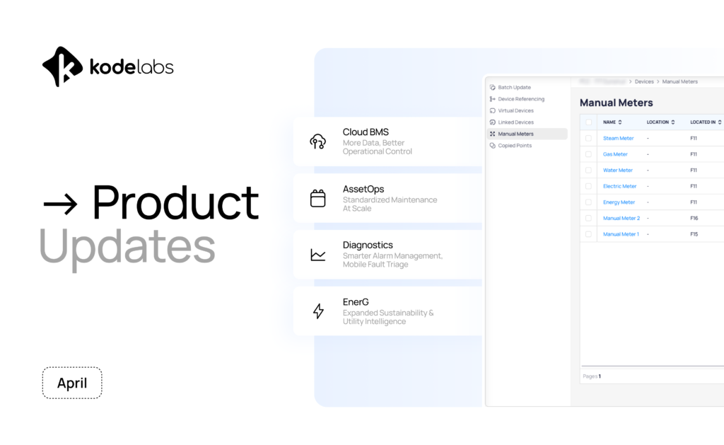
April was about bringing more intelligence into operations. This month, we introduced new capabilities that configure assets at scale, bring disconnected data into KODE OS, and strengthen emissions and utility intelligence inside EnerG. From faster dashboard performance to GHG-aligned emissions accounting, these updates are designed to help teams operate with more context, control, and confidence. […]
Read more
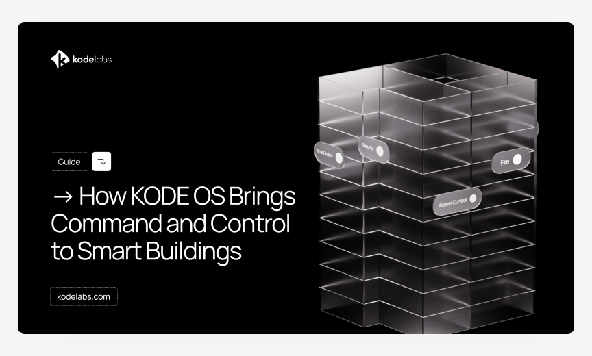
Why Smart Buildings Need More Than Software Most smart buildings today are surrounded by technology, but very few are truly unified by it. Controls, dashboards, analytics, reporting tools, energy applications, the stack keeps growing, yet operations still feel disconnected. KODE OS is built to solve exactly that problem: a single, open, agnostic operating layer that […]
Read more

For an Energy and Sustainability Manager, the day does not start with strategy. It starts with pressure. A utility spike at one site. Missing data in another. A reporting deadline that is getting closer. A carbon target that leadership wants updated. A budget variance that finance needs explained. And behind all of it, the same […]
Read more
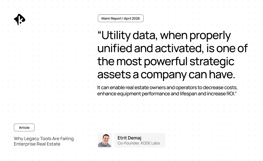
Originally published on Mann Report New energy and utility mandates now affect over 50 jurisdictions across the United States. And that number is growing. Rapidly evolving regulation across the United States is putting increasing pressure on enterprise portfolios to provide accurate sustainability reporting, identify where cost efficiencies are generated and ensure data transparency. Staying compliant […]
Read more

For product managers, especially in complex environments like smart buildings, results depend on how well teams move from idea to execution to measurable outcomes. There’s no room for handoffs or misalignment. In this edition of HR Journal, we sit down with Michael Kovalcik, Product Manager for the Diagnostics team at KODE Labs, to break down […]
Read more

What does the Workspace Occupancy & Utilization dashboard do? The Workspace Occupancy & Utilization dashboard provides a unified view of how space is actually used across portfolios, buildings, and individual spaces. Most organizations already have occupancy data, but it’s fragmented across different systems: sensor pilots, access control, Wi-Fi triangulation, and booking tools. Each source tells […]
Read more
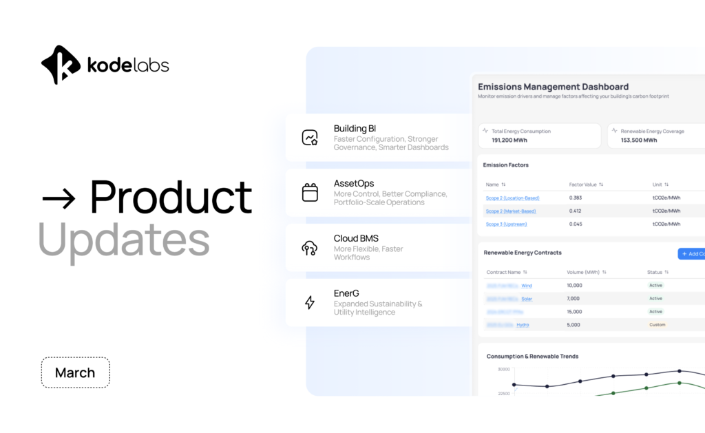
March at KODE was all about scale, control, and visibility. This month, we focused on making KODE OS easier to configure, faster to deploy across portfolios, and more powerful for managing data, maintenance, and integrations at scale. From Building BI enhancements to deeper AssetOps controls and expanded integrations, these updates are designed to reduce friction […]
Read more